Archive for July, 2015

BGP Route Reflectors & Confederations

Posted: July 23, 2015 in BGP

ibgp-6-routers-full-mesh

  • The above topology shows an iBGP full mesh setup.The topology has 6 routers that requires 15 iBGP Peerings to establish a full Mesh.
  • The formula N(N-1)/2 (where N is the amount of  routers) , used to calculate the amount of required iBGP Peerings to establish a full mesh.
  • iBGP full mesh is required because the iBGP loop prevention rule states that  ” An iBGP learned route will not be advertised to other iBGP Peers.”
  • If a router does not have full mesh connectivity with other peers , the router will not have a full view of the entire topology/Prefixes.

Confederation

  • If we apply BGP Confederations  on the above topology , the required iBGP peerings will be reduced to  8.

bgp-confederation-example

Route Reflectors

gtf

  • If we apply BGP Route Reflectors on the above topology , the required iBGP peerings will be reduced to  6.

BGP Confederations

Posted: July 23, 2015 in BGP

screenshot

  • Defined in RFC 5065, Autonomous System Confederations for BGP, confederations, like route reflectors, are used to reduce the need for fully meshed iBGP peerings in large-scale deployments. In confederation, a public AS is split into smaller Sub Autonomous Systems (Sub-ASs), which exhibit a hybrid behavior of both iBGP and EBGP. Inside a Sub-AS, the requirement for either fully meshed iBGP peerings or route reflection still applies, but between Sub-ASs, EBGP advertisement rules apply.
  • First, the BGP process is initialized using the Sub-AS number, as opposed to the normal initialization with the public AS number. Sub-AS numbers are typically in the private AS range (64512 – 65535), but technically can be any valid number, private or not. Next, the bgp confederation identifier informs the router that it is part of a confederation, with the ID number being its public AS number.
  • Any neighbor whose remote-as matches either the local Sub-AS or a number listed in the bgp confederation peers statement is considered to be part of the confederation. In the latter case, these peers are considered “confederation EBGP peers.” Neighbors whose AS matches neither the local Sub-AS nor a confederation peer AS are considered normal EBGP neighbors. The most notable difference between confederation implementations and route reflection or full mesh is the introduction of a new BGP attribute known as the AS_CONFED_SET. The confederation set, or simply confed set, is an unordered list of Sub-ASs that is prepended onto the normal AS-Path of a BGP prefix as it is passed between Sub-ASs. The confed set, however, is stripped and replaced by the confederation identifier when a prefix is advertised to a true EBGP peer.
  • Note : From a bestpath selection point of view, the entire AS_CONFED_SET counts as only one AS.

BGP Route Reflectors

Posted: July 17, 2015 in BGP

Source INE :

  • BGP route reflectors, as defined in RFC 2796, are used in large-scale iBGP deployments to reduce the need for [n*(n-1)/2] fully meshed peerings. Route reflectors accomplish this by creating an exception for passing advertisements between IBGP peers
  • A route reflector can have three types of peers: EBGP peers, client peers, and nonclient peers. EBGP peers are neighbors in a different AS number, including peers in different Sub-ASs in confederation. Client peers are iBGP neighbors that have the route-reflector-client statement configured. Non-client peers are normal iBGP peers that do not have the route reflector-client statement configured. Routing advertisements sent from the route reflector must conform to the following three rules:
  • 1. Routes learned from EBGP peers can be sent to other EBGP peers, clients, and nonclients. 2. Routes learned from client peers can be sent to EBGP peers, other client peers, and non-clients. 3. Routes learned from non-client peers can be sent to EBGP peers, and client peers, but not other non-clients.
  • Note : When a route is advertised, or “reflected,” from the route reflector to a client or nonclient, BGP attributes such as the next-hop value are not updated:

Two new attributes are added onto the reflected prefix, the Originator ID and the Cluster List:Recall that previously, loop prevention in iBGP was achieved simply by not advertising routes learned from one iBGP neighbor to another. Because route reflection violates this rule, new loop prevention must be implemented.

  • Originator ID: is set by the route reflector as the BGP router-id of the neighbor from which it learned the prefix , When any BGP speaker learns a route from an iBGP neighbor, and the Originator ID matches their own local router-id, the route is discarded.This is why it is essential that the BGP router-id value be unique throughout the entire routing domain, just like in OSPF and EIGRP.
  • Cluster List : the Cluster List, contains the Cluster-IDs of the route reflectors that the route transited through in the network. This attribute is used to prevent loops between route-reflectors, when a hierarchical design called Clustering is implemented. A “cluster” in BGP is defined as a route reflector and its clients.

Note :that because the other attributes in the prefix are not updated by the route reflector, the reflector is analogous to the DR in OSPF, and in many cases traffic does not physically transit through this device. Instead, the reflector is simply a central point for network control traffic, but not necessarily an aggregation point for traffic.

BGP Clusters

The term “cluster” refers to a route-reflector and its clients, or multiple routereflectors that service the same clients. Clustering is used to create a balance between the amount of BGP control traffic that must be maintained through peering and redundancy. Many large-scale service providers use clustering to create hierarchy in their iBGP designs by constraining clusters to different geographic regions, which reduces the number of long-haul BGP peerings that must occur.

Inter-cluster peerings ( When route reflectors are clients of each other. )

inter-cluster peerings configured as client peerings, each update message sent out results in a feedback loop of update messages received back in. With only a few prefixes in the BGP table, this may not seem like a big issue, but with the hundreds of thousands of prefixes in the Internet BGP table, these type of loops can quickly cause utilization problems.

BGP Miscellaneous

Posted: July 16, 2015 in BGP
  • The default TTL for EBGP peers is 1. This means that non-directly connected EBGP peers cannot be established, because the TTL will  expire in transit. By issuing the ebgp-multihop [ttl] command, the TTL can be increased to support your design.
  • With default EBGP sessions, a TTL of one prevents non-directly connected neighbors from forming. Additionally, IOS prevents the initiation of nondirectly connected EBGP sessions when the TTL is one (multihop is not configured), because it assumes that the TTL will expire in transit. One way of resolving this problem is to simply increase the TTL between the peers. In designs where the peers are directly connected but the peering address is a Loopback instead of the connected interface between them, the disable-connected-check neighbor option may also be used.
  • Although the ebgp-multihop & disable-connected-check  the difference between these features is that the disable-connected-check prevents cases in which the EBGP session between two devices is routed over another transit router  155.1.0.4 rcv UPDATE about 155.1.23.0/24 — DENIED due to: NEXTHOP is our own address;, because the TTL value remains 1.
  • The BGP split-horizon rule governs the route advertisements between IBGP peers, which specifies that routes learn via IBGP are never propagated to other IBGP peers.
    Note: The BGP split-horizon rule is slightly different that the split-horizon rule as in the distance vector routing protocols.
    Note: Regular split-horizon rule still govern the route advertisements between EBGP peers, in which a route is not advertised back to the EBGP peer from which the route was received.
  • RIB-failure by itself is not necessarily bad, but there are certain cases in which this disconnect between the BGP table and the routing table can cause traffic loops. By default, BGP routes that have RIB-failure can be advertised to other neighbors, because the command no bgp suppress-inactive is the default option under the routing process. To stop RIB-failure routes from being advertised, issue the bgp suppress-inactive command under the process.

as

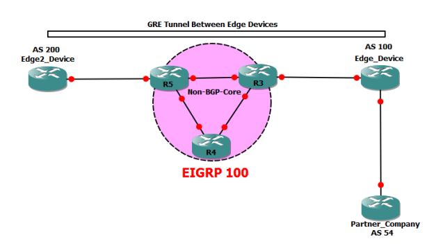
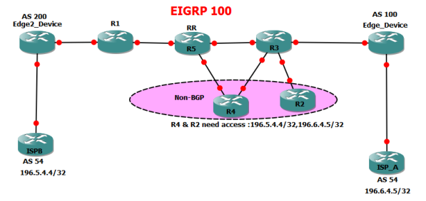
Using automatic tunneling techniques along with BGP is the core of MPLS VPNs. In this case we’ll use simple manual tunnels along with BGP to better understand possible effects. Two devices peer BGP (this could be eBGP or iBGP session) across a non-BGP-capable router cloud. This configuration means that any attempt to reach a BGP prefix across the non-BGP cloud ould result in prefix blackholing. However, if we establish a direct tunnel between the BGP peers and force all packets go across the tunnel, the non-BGP devices will never notice those packets. Thus, the “unknown” addresses will be hidden from the “core” network, only appearing at the edge routers that know about them. Notice the trick used in the solution. Although the “core” IP addresses are used for BGP peering, next-hops in BGP prefixes are modified to point to the tunnel endpoints. Alternatively, you could have peered directly off the tunnel endpoints or even used policy routing to divert packets to the tunnel interfaces:

oko

Enabling BGP on all transit devices in the AS is one way to ensure that all routers have full external routing information. This solution is scalable, because it avoids feeding large BGP tables into IGP. In some situations, you cannot enable BGP on all routers in your network. This may be the case of an enterprise network, in which only border routers peer eBGP with
the ISP. In such situations, it is common to advertise a default route from the border routers toward the rest of the network.
There could be even more complicated scenarios, such as migrating your network or gradually enabling BGP on all devices. In situations like these, you may find that iBGP peers are separated by non-BGP cloud or that non-BGP speakers need BGP
routes from the devices that learned them via iBGP (no eBGP!). So what’s wrong with redistributing iBGP prefixes into IGP? As you remember, BGP uses AS_PATH attributes to detect routing loops. When exchanging iBGP routes, AS_PATH
attributes are not prepended and thus the route loop prevention technique does not work. Because of that, feeding iBGP prefixes into an IGP may result in routing loops, because the “split-horizon” rules for BGP prefixes may be broken. To make
this situation even worse, iBGP has the AD value that makes it less preferred than any IGP. Thus, iBGP prefixes redistributed into an IGP may preempt iBGP-learned prefixes on other iBGP speakers. To prevent the above issues, iBGP-learned prefixes are not automatically redistributed into IGP when you issue the statement redistribute bgp under any IGP process on the router, only eBGP prefixes are redistributed. To make iBGP redistribution possible, you need an additional statement configured under the BGP process: bgp redistribute internal . Be very careful when enabling this feature, because you may quickly end up with routing loops, and try to avoid multiple points of iBGP to IGP redistribution.

Peer Groups

The major benefit you achieve when you specify a BGP peer group is that a BGP peer group reduces the amount of system resources (CPU and memory) necessary in an update generation. In addition, a BGP peer group also simplifies the BGP configuration. A BGP peer group reduces the load on system resources by allowing the routing table to be checked only once, and updates to be replicated to all peer group members instead of being done individually for each peer in the peer group. Based on the number of peer group members, the number of prefixes in the table, and the number of prefixes advertised, this can significantly reduce the load. It is recommended that you group together peers with identical outbound announcement policies.

router bgp 100
bgp log-neighbor-changes
neighbor 1.1.1.1  peer-group SPOKES
neighbor DMVPN_SPOKES peer-group
neighbor DMVPN_SPOKES remote-as 100
neighbor DMVPN_SPOKES route-reflector-client

BGP Update Source.

Posted: July 15, 2015 in BGP
  • updatesrc
  • Because BGP peerings use TCP for transport, it is not a requirement that neighbors
    be directly connected. When neighbors are not directly connected, the choice of IP
    addresses used in peering can greatly affect the redundancy design of a BGP
    network.
  • Normally the IP source address used in a BGP packet is the IP address of the
    outgoing interface in the routing table.
  • The TCP server of the BGP session must approve where the session is coming from. If the SYN packet arrives from an
    address that is not specified in a neighbor statement, the connection is refused ( Reset )
  • This exercise is based on the  BGP Peering  between R15 and R12

R15#sh ip bgp summary
Neighbor        V           AS MsgRcvd MsgSent   TblVer  InQ OutQ Up/Down  State/PfxRcd
10.4.0.1        4          200       4       4        1    0    0 00:00:25     

R12#sh ip bgp summary
Neighbor        V           AS MsgRcvd MsgSent   TblVer  InQ OutQ Up/Down  State/PfxRcd
10.4.0.2        4          200       5       5        1    0    0 00:01:11        0

  • In this setup iBGP Peering is established via a shared segment 10.4.0.0/24 , meaning R12 BGP source update will be 10.4.0.1 and R15 source will be 10.4.0.2
  • In our topology R15 is the Server , and its receiving a BGP message from R12 with  Source of 10.4.0.1 which corresponds to its neighbor statement.

The issue with our design is that our BGP Peering has no redundancy if SW4 goes down , the BGP peering is lost. Even though we have an alternate R13 router we can use.An alternate solution is to peer using our loopback addresses of R12 & R15.This will allow the BGP Session to be re-routed via R13 if Sw4 goes down therefore maintaining our BGP session between R12 & R15.

  • First will apply the Neighbor statements pointing to the loopbacks of R12 & R15 without specifying the update source.

R12#sh ip bgp summary
Neighbor        V           AS MsgRcvd MsgSent   TblVer  InQ OutQ Up/Down  State/PfxRcd
192.168.15.15   4          200       0       0        1    0    0 00:01:15 Idle

R15#sh ip bgp summary 
Neighbor        V           AS MsgRcvd MsgSent   TblVer  InQ OutQ Up/Down  State/PfxRcd
192.168.12.12   4          200       0       0        1    0    0 never    Idle

  • As we can see the BGP Peering is not coming up , even through R12 & R15 can ping each others loopbacks via the underlying IGP ( EIGRP ).
  • In the background  the Peers are busy trying to establish the peering  , but they keep resetting each other peering’s because the update source does not match the neighbor statements.
  • R12 is expecting a TCP SYN with a Source of 192.168.15.15( its neighbor statement ) but is getting 10.4.0.2
  • R15 is expecting a TCP SYN with a Source of 192.168.12.12( its neighbor statement ) but is getting 10.4.0.1

tcp bgp

  • To resolve the issue we need to specify the update source of Loopback 0 , which we can specify on one side. The side were we specify the update source will automatically become the TCP client.
  • The update source of loopback 0  is added to R15 , this means when R15 sends his TCP SYN to R12 with a source of  192.168.15.15 which matches R12’s neighbor statement.

R15#sh ip bgp neighbors 192.168.12.12  

jjjj

iBGP & eBGP

Posted: July 14, 2015 in BGP

ibgp

  • BGP is an application running on TCP port 179
  • The main purpose of BGP is to advertise prefixs(subnets ) with the next Hop values associated with them.
  • BGP does not have its own transport so it  relies on the underlying IGP( Static , EIGRP , OSPF , RIP & IS-IS ) for transport , this is why BGP considered an application rather than a routing protocol.
  • BGP OPEN Messages – used during the initial BGP Peer establishment, carries BGP parameters used to establish a BGP peer.
  • BGP UPDATE Messages – carries topology change information
  • BGP Keepalive – Sent every 60 sec by default , Hold down timer is 180 Seconds.
  • BGP Ack – Used to Acknowledge OPEN , UPDATE , Keepalive Messages.
  • For two BGP Speakers to form a peering they have to go  through a normal  TCP 3 WAY Handshake.

3 WAY TCP Handshake

  • Below output shows a BGP session establishment between R11 & R15

ibgp tcp

  • R15(10.3.0.1) initiates the TCP Handshake by sending a SYN to with to destination TCP port of 179.
  • Because R15 initiated the connection to TCP port 179 it automatically becomes the client for the session.
  • If both BGP peers attempt to establish the connection at the same time, RFC 4271 (A Border Gateway Protocol 4) defines a “BGP Connection Collision Detection” mechanism, in which essentially the session originated from the device with the higher BGP router-id is maintained, and the secondary session is dropped.
  • After the 3 Way Handshake is completed routers R15 & R11 will send each other OPEN Massages , these massages include  BGP Parameters ( AS number, BGP version , Hold Timer  , Optional Parameters etc ).

iBGP

  • BGP speakers in the same AS( Autonomous System ) are considered as iBGP peers.
  • The main rule of thumb for iBGP is : Do not advertise iBGP learned routes to other iBGP peers unless exceptions such as route reflection or confederation are implemented.
  • If Route reflection or confederation is not is use ,  a full-mesh of iBGP is required for all iBGP speakers to have fully converged BGP Tables.
  • The iBGP  TTL for  outbound sessions is set to 255.This means that the iBGP neighbors need not be directly connected, as long as IGP reachability exists between them.

eBGP

  • BGP speakers in different AS( Autonomous System ) are considered as eBGP peers.
  • By default  eBGP  TTL for outbound sessions is set to 1.This means that the eBGP peers need to be directly connected to form a peering.If the TTL value is exceeded the packets are dropped.
  • Note :  When iBGP routers learn prefixes from their eBGP peers they do not default  update the next-hop value when they advertise the prefixes to their iBGP peers .If the iBGP peers do not have a route to the next-hop value in the prefix, bestpath selection fails and the route cannot be used.

eigrpThis scenario is based on User_A trying to get to his server ( 196.6.6.6 ) in an EIGRP routed domain.

  • Below is EIGRP topology output on R10.

topolgogy

  • The eigrp topology shows   : FD  is the Feasible Distance 161280 – is my(R10) metric to get to my server ( 196.6.6.6)
  • The number is 158720 that’s the Reported Distance – is my Neighbors ( R9 ) metric ( FD ) to get to the Server (196.6.6.6)

If we look below at the EIGRP Topology All-links output see that R10 actually has two link to get to the Server ( 196.6.6.6).

topology all links

  • The alternate route to get to Server (196.6.6.6 ) is not being installed in the topology database because its failing the feasibility condition.
  • Feasibility condition – My neighbors(R17)  Reported Distance ( his feasible distance/metric ) should be less than my( R10) Feasible distance (FD).
  • So R10s alternate route to the server ( 196.6.6.6 ) is via 10.4.0.2  and his Reported Distance is 161280 , which is equal to R10 Feasible distance , because the values are equal : R17 fails the Feasibility Condition.

nssa

  • R5 is redistributing external prefix 5.5.5.5/32 into the OSPF Domain.
  • Area 1 currently configured as NSSA area, meaning the external route is seen as Type 7 LSA in Area 1
  • Not-So-stubby areas  were designed to allow stub areas to have the ability to advertise external routes into the OSPF Domain.

nssa

  • R5’s OSPF database shows Type 7 LSA  with the Link ID representing the prefix 5.5.5.5 and ADV Router is the R5 ( advertising router) .
  • When the  LSA gets to the ABR R4 , the LSA is converted into a Type5 LSA and is advertised into other OSPF areas.
  • See below OSPF Database of R2 in Area 0

nssa 2

  • R2 Database shows that  5.5.5.5  LSA has been turned into a Type 5 LSA  & the advertising router is  the ABR ( 9.9.9.9 )
  • lets look at the  sh ip ospf database external 5.5.5.5  output.

ext

  • The Type 5 LSA from an the  NSSA stub has a Forward Address of 10.3.0.1 which is the Router ID of the router in Area 1 that Originated the Prefix.

OSPF DatabaseLets looks at R5 OSPF Database:

r5 database

Router LSA ( Router  Link States )

  • Router LSA – generated by every router in the OSPF Domain.
  • Describes individual routers interfaces in a specific area , in our case we looking at Area 1
  • LINK ID stands for Router ID
  • Link Count – is the amount of interfaces each router has in Area 1.

Network LSA ( Net Link States )

  • Shows the DR for an Ethernet Segment
  • Link ID is the IP address on the interface that’s currently DR on the Ethernet Segment
  • Note : you can have multiple Ethernet (DRs) segments on one area, in our example we have two DR’s  in area 1 , 10.10.1 and 10.3.0.1

Summary  LSA ( Summary Net  Link States )

  • Shows LSAs  from other areas
  • LINK ID –  is the network address of  the LSA.
  • Its Area 0’s job to advertise summary routes into other non-back borne areas

ASBR (Summary ASB  Link States )

  • shows the ASBR in the OSPF Domain
  • LINK ID – ASBR Router ID.

ASBR summary

  • Advertising Router : 9.9.9.9 – the router that’s advertising ASBR LSA , which is the ABR R4
  • Link State ID : 1.1.1.1 – the router ID of the ASBR

External LSA

  • shows the external routes we are learning.
  • LINK ID is the Network address of the external Prefix

lsa external

  • Forward Address 0.0.0.0 : This is a special field used on OSPF type 5 and 7 LSAs to convey the information of the “external route source”. The purpose of FA is to optimize forwarding in situations where the external route source is connected to a shared segment. Because the FA is null traffic to the External is routed towards the advertising router ( 1.1.1.1).

screenshot

                            Everything you will read below is based on the above Topology ( GNS3)

  • OSPF Inter area ( prefixes from other areas within the OSPF Domain )  can only be  summarized on the ABR.
  • OSPF external prefixes can only be  summarized on the ASBR or the ABR that converts type 7 LSA to type 5 LSA.
  • Prefix Filtering techniques like Distribute lists  when applied in OSPF do not affect the OSPF Database rather affect routing table outlook E.G if you deny prefix A from entering Router_D via a distribute list , prefix A wont be installed in the routing table but will still be installed in the OSPF Database , RIP and EIGRP on the other hand will not install the denied prefix in both the Database and the routing table.
  • Area Range , Summary address & filter-lists can change the OSPF database outlook ( structure) not filtering  techniques like distribute lists.
  • NSSA & NSSA no-summary were designed to allow Stub OSPF networks the ability to advertise external routes into the OSPF Domain.
  • The Passive Interface feature helps in preventing routers from forming neighbor relationships with untrusted devices on the network , this means the router will not send out hellos out that interface  . But this works a bit differently with  RIP , as we know RIP does not use HELLOs and theirs no neighbor relationships formed between adjacent routes.
  • If passive interface is enabled on a RIP enabled interface , the interface can still receive RIP updates from the adjacent router , to avoid unwanted routes the passive interface command should applied on both ends.
  • With RIP and OSPF an Authentication mis-match does not result in the Neighbor going down immediately ( triggered ) , the neighborship will only go down once the Hold timer has expired.
  • EIGRP Authentication mis-match will result in the neighbor-ship being immediately shut down ( Triggered ).
  • A neighbor relationship cannot occur if two OSPF neighbors have different MTU
    values on their interfaces. If the MTU difference is by design, the interface-level
    command ip ospf mtu-ignore removes this requirement from the adjacency
    establishment.
  • The OSPF command database-filter all out is similar in operation to the passive interface command in RIPv2. This feature allows the formation of OSPF neighbors,
    because hello packets are not filtered out, but it stops the advertisements of all LSAs out the interface or to the neighbor in question.The command is applied at interface level or under the neighbor statement in DMVPN type scenarios.
  • When access-lists are used  in route filtering with distribute lists the following applies ;  (1) Standard Access lists – matches prefix/subnet  (2) Extended Access List – Source field matches gateway(next-hop ) and destination field  matches the prefix/subnet.
  • OSPF null 0/Discard Route : When summarization is configured in OSPF, similar to EIGRP and BGP, a matching route to Null0 for the summary is installed locally in the routing table. This “discard”
    route is used to prevent the forwarding of traffic toward a shorter match, such as a default route, if no specific route toward the actual destination exists in the network. The automatic origination of the discard route can be disabled with the no discardroute [internal | external], where internal refers to inter-area summarization performed with the area range command, and external refers to redistributed summarization performed with the summary-address command.