Archive for January, 2016

In this post, we will examine PAP and CHAP forms of PPP authentication. The emphasis here will be on the fact that these technologies are one-way in nature. So many of my CCIE-level students believe that they must be configured in a bidirectional configuration. I guess this is because it is what traditional Cisco classes always demonstrate at the CCNA and CCNP levels.

OK – I have pre-configured two routers, R1 and R2, they are connected by their Serial 0/0 interfaces. Let us begin with R1 as a PPP PAP server, and the R2 device as the PPP PAP client. If you ALWAYS think of these technologies (PAP and CHAP) in terms of CLIENT and SERVER commands, you will be in excellent shape.

Let us begin with R1 playing the role of a PAP server and R2 playing the role of a PAP client. In other words, R1 will be the device that requires authentication, and R2 will be the device that must respond with the correct authentication information.

R1#conf t
Enter configuration commands, one per line.  End with CNTL/Z.
R1(config)#username ROUTER2 password cisco
R1(config)#int s0/0
R1(config-if)#encapsulation ppp
*Mar  1 00:04:47.359: %LINEPROTO-5-UPDOWN: Line protocol on Interface Serial0/0, changed state to down
R1(config-if)#ppp authentication pap

Here is the configuration of the PAP client:

R2#conf t
Enter configuration commands, one per line.  End with CNTL/Z.
R2(config)#int s0/0
R2(config-if)#encapsulation ppp
R2(config-if)#ppp pap sent-username ROUTER2 password cisco
R2(config-if)#end
R2#
*Mar  1 00:08:40.539: %SYS-5-CONFIG_I: Configured from console by console
R2#
*Mar  1 00:08:41.647: %LINEPROTO-5-UPDOWN: Line protocol on Interface Serial0/0, changed state to up
R2#

Study these server and client commands above carefully. Also, notice how the moment the correct commands are entered on the client, the link is established.

Now it is time to review the CHAP configuration. We will have the R2 device serve as the CHAP server and the R1 device function as the CHAP client. First the R2 CHAP server commands:

R2#conf t
Enter configuration commands, one per line.  End with CNTL/Z.
R2(config)#username R1 password cisco
R2(config)#int s0/0
R2(config-if)#encapsulation ppp
R2(config-if)#ppp authentication chap

Now the CHAP client configuration on R1:

R1#conf t
Enter configuration commands, one per line.  End with CNTL/Z.
interface Serial2/0
 ip address 203.3.18.1 255.255.255.252
 encapsulation ppp
 ppp chap hostname R1
 ppp chap password 0 cisco

Notice that once the matching shared secret password of cisco is placed on the client system, the link is restored.

IPv6 over MPLS

Posted: January 22, 2016 in Interior gateway protocols (IGP)

v6.PNG

v61.PNG

IPv6 BGP

Posted: January 20, 2016 in Interior gateway protocols (IGP)

bgp 1.PNG

bgp 2

Configuration

#sh bgp ipv6 unicast

#sh bgp ipv6 unicast summary

Route Reflector

router bgp 100
bgp log-neighbor-changes
no bgp default ipv4-unicast
neighbor IPV6_IBGP peer-group
neighbor IPV6_IBGP remote-as 100
neighbor IPV6_IBGP update-source Loopback0
neighbor 2001:150:2:2::2 peer-group IPV6_IBGP
neighbor 2001:150:3:3::3 peer-group IPV6_IBGP
neighbor 2001:150:4:4::4 peer-group IPV6_IBGP
neighbor 2001:150:5:5::5 peer-group IPV6_IBGP
neighbor 2001:150:6:6::6 peer-group IPV6_IBGP
neighbor 2001:150:7:7::7 peer-group IPV6_IBGP
neighbor 2001:150:8:8::8 peer-group IPV6_IBGP
address-family ipv4
exit-address-family

address-family ipv6
neighbor IPV6_IBGP route-reflector-client
neighbor 2001:150:2:2::2 activate
neighbor 2001:150:3:3::3 activate
neighbor 2001:150:4:4::4 activate
neighbor 2001:150:5:5::5 activate
neighbor 2001:150:6:6::6 activate
neighbor 2001:150:7:7::7 activate
neighbor 2001:150:8:8::8 activate
exit-address-family

Spoke

router bgp 100
bgp log-neighbor-changes
no bgp default ipv4-unicast
neighbor 2001:150:1:1::1 remote-as 100
neighbor 2001:150:1:1::1 update-source Loopback0

address-family ipv4
exit-address-family

address-family ipv6
neighbor 2001:150:1:1::1 activate
exit-address-family

Using Link-Local Address

router bgp 9
bgp log-neighbor-changes
no bgp default ipv4-unicast
neighbor FE80::7%Ethernet0/1.79 remote-as 100
neighbor FE80::7%Ethernet0/1.79 update-source Ethernet0/1.79

address-family ipv4
exit-address-family

address-family ipv6
network 2001:150:9:9::9/128
neighbor FE80::7%Ethernet0/1.79 activate
exit-address-family

Using IPv4 as Transport

By default if you use IPv4 as transport for Ipv6 , the IPv6 NLRI prefix’s will have a next hop of IPv4 in-corded as an IPv6  , this next hop recursion will fail. To fix this use the no bgp default ipv6-nexthop command.

router bgp 10
bgp log-neighbor-changes
no bgp default ipv4-unicast
no bgp default ipv6-nexthop
neighbor 155.1.108.8 remote-as 100

address-family ipv4
exit-address-family

address-family ipv6
redistribute connected
neighbor 155.1.108.8 activate
exit-address-family

OSPFv3

Posted: January 19, 2016 in Interior gateway protocols (IGP)

OSPF V3 1

OSPF V3 2.PNG

OSPF V3 3.PNGOSPF V3 4.PNG

OSPF V3 5.PNG

OSPF V3 6.PNG

IPV6 EIGRP

Posted: January 15, 2016 in Interior gateway protocols (IGP)

eigrp

EIGRP TYPES:

NAMED EIGRP 

IPv6 Format

router eigrp a

address-family ipv6 unicast autonomous-system 1

topology base
exit-af-topology
eigrp router-id 2.2.2.2
exit-address-family

IPv4 Format

router eigrp a

address-family ipv4 unicast autonomous-system 1

topology base
exit-af-topology
network 40.40.40.2 0.0.0.0
network 192.168.0.2 0.0.0.0
exit-address-family
!


CLASSIC EIGRP

ipv6 router eigrp 1
eigrp router-id 1.1.1.1

interface Loopback0
ipv6 address 2011::1/128
ipv6 eigrp 1

interface FastEthernet0/0
ipv6 address 2001::1/64
ipv6 eigrp 1

IPv4 Format

router eigrp 1
network 40.40.40.1 0.0.0.0
network 192.168.0.1 0.0.0.0

DMVPN IPv6

Posted: January 15, 2016 in Interior gateway protocols (IGP)

dm ipv6.PNG

Config Sample

HUB
ipv6 address 2001:155:1:0::5/64
ipv6 address fe80::5 link-local
ipv6 nhrp authentication NHRPPASS
ipv6 nhrp map multicast dynamic
ipv6 nhrp network-id 1
SPOKE
ipv6 address 2001:155:1:0::2/64
ipv6 address fe80::2 link-local
ipv6 nhrp authentication NHRPPASS
ipv6 nhrp network-id 1
ipv6 nhrp map 2001:155:1:0::5/128 169.254.100.5
ipv6 nhrp nhs 2001:155:1::5
ipv6 nhrp map multicast 169.254.100.5


dm ipv6 1


IPv6 Routing

Posted: January 14, 2016 in Interior gateway protocols (IGP)

v1

v2
R3(config)#vrf upgrade-cli multi-af-mode common-policies

IPv6

Posted: January 12, 2016 in Interior gateway protocols (IGP)

IPv4 Dotted Decimal

  • d.d.d.d
  • d = one byte

Ipv6 Hexadecimal

  • hhhh:hhhh:hhhh:hhhh:hhhh:hhhh:hhhh:hhhh
  • hh = one byte

IPv6 Address Types 

IPv6

  1. link local address 
  • FE80::/10 (1111 1110 10 )
  • Equivalent to 169.254.0.0/16 in IPv4
  • its un-routable
  • stateless Address Auto-configuration ( SLAAC)
  • Neighbor Discovery
  • Router Discovery

2.  IPv6 Unique Local address 

  • ULA is private Use IPv6 addressing ( FC00::/7( 1111 110)
  • Equivalent to RFC 1918  ( 10.0.0.0/8, 172.16.0.0/12, 192.168.0.0/16
  • Like unique not not routable via global BGP
  • NAT required to route this via the global internet.

3. IPv6 Global Unicast Addresses

  • IANA Currently allocating 2000::/3
  • Per RFC end hosts must ;
  • Have 64-bit interface ID ( nnnn:nnnn:nnnn:nnnn:hhhh:hhhh:hhhh:hhhh/64)
  • Use EUI-64 Format for interface ID

Modified EUI-64 Addressing

  • Ethernet MAC to EUI-64 conversion
  • invert Universal/local(U/L) bit
  • 7th most significant bit
  • insert padding 0xFF 0xFE in the middle
  • EG : aabb.cc00.0110 =  FE80::A8BB:CCFF:FE00:0110
  • aa ( 1010 1010)  and Convert 7th most significant bit to 0 or 1 = A8 ( 1010 1000)

IPv6 Address Resolution – ICMPv6 Neighbor Discovery 

  • ICMPv6 ND used for layer 3 to layer 2 resolution
  • Equivalent to IPv4 ARP.

IPv6 Neighbor Discovery Messages

  • Neighbor Solicitation (NS ) – Equivalent of ARP Request ( i want to use IP X , can i use it , is there anyone using the same IP on my segment )
  • Neighbor Advertisement (NA ) – Equivalent of ARP reply ( hi guys my name IP X and i have the following MAC address Y , please add me to your ICMPv6 (ND )Table for routing lookups )
  • Router Solicitation( RS ) ( hi guys i have auto-config setup , i need an IP )
  • Router Advertisement ( RA) ( hi, please use the following IP , i also have DHCP and DNS options for you.)

IPv6 2

PING TEST LINK Local

IPv6 host A pinging IPv6 host B

R1#ping FE80::C802:25FF:FEE0:0 source FE80::C801:2AFF:FE50:0
Output Interface: fastethernet0/0
Type escape sequence to abort.
Sending 5, 100-byte ICMP Echos to FE80::C802:25FF:FEE0:0, timeout is 2 seconds:
Packet sent with a source address of FE80::C801:2AFF:FE50:0%FastEthernet0/0
!!!!!
Success rate is 100 percent (5/5), round-trip min/avg/max = 16/29/76 ms
R1#

icmp10

  • Works the same as ARP in IPv4
  • PC A sends a Neighbor solicitation to PC B , trying to map the known link local destination of FE80::C802:25FF:FEE0:0  to the destination MAC address.
  • PC B receives the request and reply’s with a Neighbor Advertisement.

PING TEST LINK Global

IPv6 host A pinging IPv6 host B

R1#ping 2001::3
Type escape sequence to abort.
Sending 5, 100-byte ICMP Echos to 2001::3, timeout is 2 seconds:
!!!!!
Success rate is 100 percent (5/5), round-trip min/avg/max = 4/27/88 ms

icmp100

IPv6 SLAAC ( IPv6 Stateless Address Auto-configuration)

  • automatically assigns IPv6 adress for every on-link prefix
  • works only with /64s on the link
  • Host uses Duplicate Address Detection( DAD ) to verify uniqueness of generated address
  • SLAAC is not DHCPv6 ( does not include options eg . DNS Server

SLAAC and DHCPv6 

  • (1) SLAAC commonly works along with DHCPv6
  • options are set in router advertisement (RA ) messages
  • Tells the host that there is a DHCPv6 server available for addressing options
  • (2) Other-Config-Flag
  • Use DHCPv6 to receive just addressing options ( DNS,TFTP ,etc )
  • ipv6 nd other-config-flag
  • (3) Managed-Config-Flag
  • Use DHCPv6 for both adressing and options
  • ipv6 nd managed-config-flag


DMVPNs

Posted: January 7, 2016 in Interior gateway protocols (IGP)

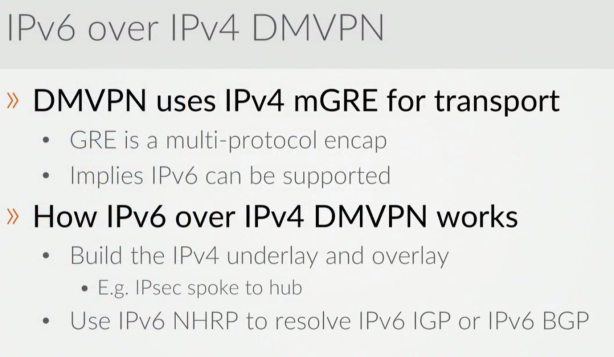
With the legacy Point to Point tunnels like GRE , you can only setup tunnels between two end-points. DMVPN gives us the ability to configure point to multi-point tunnel with direct spoke to spoke communication.

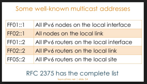
DMVPN’s allows for Point to Multi-point hub to spoke communications by the making use of the NHRP ( Next-Hop-Resolution Protocol ). NHRP work the same way as ARP works in Ethernet ( Resolution between MAC  to IP). NHRP does IP to IP Resolution ( NHRP tells  clients when you  want to send traffic to a particular destination or specifically to a specific spoke what their mapping between their underlay address( NBMA) and their ovelay address which is the VPN address.)
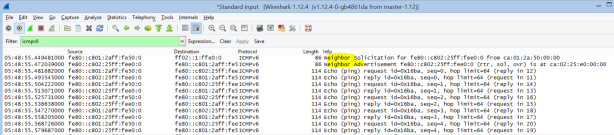
NHRP Sniff.

Spoke Capture

169.254.100.1 is the Spoke registering to 169.254.100.5 the HUB.

NHRP


DMVPN has 3 phases ;

PHASE 1

NHRP still required for Spoke registration to hub

No spoke-to-spoke tunnels

Summarization/default routing at hub is allowed.

Next-hop on spokes is always changed by the hub

OSPF can run in any mode.

Phase 1 Config 

HUB
interface Tunnel0
ip address 155.1.0.5 255.255.255.0
ip mtu 1400
no ip next-hop-self eigrp 1
no ip split-horizon eigrp 1
ip nhrp authentication NHRPPASS
ip nhrp map multicast dynamic
ip nhrp network-id 1
ip tcp adjust-mss 1360
delay 1000
tunnel source Ethernet0/1.100
tunnel mode gre multipoint
tunnel key 150

Spoke
interface Tunnel0
ip address 155.1.0.2 255.255.255.0
ip mtu 1400
ip nhrp authentication NHRPPASS
ip nhrp map 155.1.0.5 169.254.100.5
ip nhrp map multicast 169.254.100.5
ip nhrp network-id 1
ip nhrp holdtime 300
ip nhrp nhs 155.1.0.5
ip tcp adjust-mss 1360
tunnel source Ethernet0/1.100
tunnel destination 169.254.100.5
tunnel key 150


PHASE 2

NHRP required for Spoke registration to hub
NHRP required for Spoke to spoke registration
Spoke-to-Spoke tunnel triggered by spoke.
Summarization/dafault routing at HUB is NOT allowed
Next-hop on spokes is always preserved by the hub
Multi-level hierarchy required hu daisy-chaining

You should  run OSPF in Broadcast & No-Broadcast mode in-order to preserve the next-hop values. The DR does not modify OSPF next hop values.

EIGRP by default updates the next values from the HUB to the spokes , this prevents spoke to spoke communication as the next hop will now point to the hub instead of individual spokes. EIGRP has command to prevent the HUB from changing the next hop value to its self (no ip next-hop-self eigrp 1)

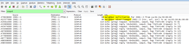
In Phase 2 the spoke sends NHRP Resolution requests to the other spokes , in order to resolve the NBMA Address  and the  Private Address. You will always see that the first packet sent always routes via the HUB , then the packets there after are routed straight between spokes.

Spoke Capture

NHRP p2

Phase 2 Config

HUB

interface Tunnel0
ip address 155.1.0.5 255.255.255.0
no ip redirects
ip mtu 1400
no ip next-hop-self eigrp 1
no ip split-horizon eigrp 1
ip nhrp authentication NHRPPASS
ip nhrp map multicast dynamic
ip nhrp network-id 1
ip tcp adjust-mss 1360
delay 1000
tunnel source Ethernet0/1.100
tunnel mode gre multipoint
tunnel key 150

Spoke
interface Tunnel0
ip address 155.1.0.2 255.255.255.0
no ip redirects
ip mtu 1400
ip nhrp authentication NHRPPASS
ip nhrp map 155.1.0.5 169.254.100.5
ip nhrp map multicast 169.254.100.5
ip nhrp network-id 1
ip nhrp holdtime 300
ip nhrp nhs 155.1.0.5
ip tcp adjust-mss 1360
tunnel source Ethernet0/1.100
tunnel mode gre multipoint
tunnel key 150

Phase 3

NHRP required for spoke registration to hub
NHRP required for spoke-to-spoke resolution
when a hub receives and forwards out the same interface
send NHRP redirect message back to packet source
forward original packet down to spoke via RIB
summarization/default routinh at hub is allowed
results in NHRP routes for spoke to spoke tunnel
With no-summary, NHO is performed for spoke to spoke tunnel
next hop is changed from hub IP to spoke IP
Next-hop on spokes is always changed by the hub
because of this , NHRP resolution is triggered by hub
Multi-level hierarchy  without daisy-chaining.

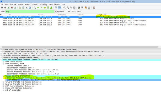
Phase3 NHRP makes use of the NHRP Traffic Indication massage , this message allows the HUB to trigger the NHRP process for the spokes.

Spoke Capture

NHRP P3

Phase 3 Config

HUB

interface Tunnel0
ip address 155.1.0.5 255.255.255.0
no ip redirects
ip mtu 1400
no ip next-hop-self eigrp 1
no ip split-horizon eigrp 1
ip nhrp authentication NHRPPASS
ip nhrp map multicast dynamic
ip nhrp network-id 1
ip nhrp redirect
ip tcp adjust-mss 1360
delay 1000
tunnel source Ethernet0/1.100
tunnel mode gre multipoint
tunnel key 150

Spoke
interface Tunnel0
ip address 155.1.0.2 255.255.255.0
no ip redirects
ip mtu 1400
ip nhrp authentication NHRPPASS
ip nhrp map 155.1.0.5 169.254.100.5
ip nhrp map multicast 169.254.100.5
ip nhrp network-id 1
ip nhrp holdtime 300
ip nhrp nhs 155.1.0.5
ip nhrp shortcut
ip tcp adjust-mss 1360
tunnel source Ethernet0/1.100
tunnel mode gre multipoint
tunnel key 150

Note :

Phase 2 : NHRP process is triggered by the spoke  ,  and the NHRP resolution is always trying to resolve the next-hop value.

Phase 3 : NHRP process is triggered by the HUB  ,  and the NHRP resolution is always trying to resolve the final destination.

Phase2 & 3 :  For every prefix you send traffic to a unique DMVPN tunnel is created.

==============================================================
Interface: Tunnel0, IPv4 NHRP Details
Type:Spoke, NHRP Peers:2,

# Ent Peer NBMA Addr Peer Tunnel Add State UpDn Tm Attrb
—– ————— ————— —– ——– —–
3 169.254.100.3

155.1.0.3 UP 00:02:38 DT2
1 169.254.100.5 155.1.0.5 UP 00:19:31 S

R1#sh ip nhrp
1.1.1.1/32 via 155.1.0.3
Tunnel0 created 00:00:35, expire 00:04:24
Type: dynamic, Flags: router rib nho
NBMA address: 169.254.100.3
150.1.3.3/32 via 155.1.0.3
Tunnel0 created 00:03:09, expire 00:01:50
Type: dynamic, Flags: router rib nho
NBMA address: 169.254.100.3
155.1.0.3/32 via 155.1.0.3
Tunnel0 created 00:03:09, expire 00:04:24
Type: dynamic, Flags: router nhop rib nho
NBMA address: 169.254.100.3
155.1.0.5/32 via 155.1.0.5
Tunnel0 created 00:20:03, never expire
Type: static, Flags: used
NBMA address: 169.254.100.5